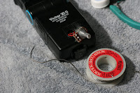
 A little over a week ago I learned that I can very easily modify my Vivitar 3500/35-D flashes to have manual power output control. Previously I tested the different settings on the flash. To give me full manual control I have replaced the photo resistor with a potentiometer. This should work with all Vivitar flashes that use a photo resistor to adjust light output. This mod is quite easy and only took about 15 minutes the second time I did it. The 3500 has a separate module where this circuitry is housed. I know some Vivitar models are one unit, so be aware that flashes have a high voltage capacitor in them and you can shock yourself.
 I found that a 50 kilohm log potentiometer works best. I set up a test rig attaching the two wires from the photo resistor to a bread board which I plugged the variable resistor into. I had previously measured the resistance of the photo resistor and found it was a megohm when the sensor was taped up. I had read that some others had used a 100k pot with good results. I thought I'd go a step up and was going to get a 250k. The electronic store was out of them, and only had one 100k, so I got that and two 500ks. After testing the potentiometers, and later, static resistors, I found that above 50k there is little difference between the strongest auto setting (the orange dot) and full power (M). So I returned the pots for two 50ks, one for each of my flashes. I also found in the tests that the flash is more sensitive on the low end of the resistance spectrum so I went with an audio taper (log) potentiometer rather than a linear one.
First, separate the module from the flash body and remove the 4 screws holding the top to the body.

Be careful pulling the unit out since wires are attached to a pcb at the bottom of the module.

The photo resistor is held by tabs on the inside of a module. Use a small screwdriver to top out the sensor. The sensor itself is in a bigger housing. Pop it out.

Cut the two wires to the photo resistor and strip them. The wires are wrapped around another set of wires inside, so I unwound them and pulled them through the top so I could get my wire strippers on them. This also gave me more length to work with. You can now close the module back up. Just make sure the switches line up when putting it together and no wires get caught on them.

The potentiometers I got are rather large for this purpose. Something small enough to fit in the module housing is ideal. I got the idea to use plastic bottle caps as a housing came from ukespresso who did this mod on his Vivitar 2800. I didn't feel like pulling the drill out so I cut wholes out with a pocket knife. To get the pots to fit under the caps I clipped the tabs as well as a tab on the top of the base.

Here you can see the pot soldered in. I used the top two pins on the pot since this raises the flash power by turning clockwise.

And the finished product. I used some double stick tape to attach the pot to the flash body. I sanded it a bit and cleaned both surfaces with rubbing alcohol. It feels strong. I then painted the cap black. I'll probably paint tick marks on the cap so I can track my power settings.

This is the difference between the dial at the lowest and highest settings. Remember that the range can be increased further by using the three color settings on the back, red being the weakest and orange being the strongest.


Feel free to ask me any questions on the process.
more diy photo


No comments:
Post a Comment